Le monde de Karpok
Communiquons librement...

Le mot du jour
Si Zeus voulait écouter les voeux des hommes, tous périraient, car ils demandent beaucoup de choses qui sont nuisibles à leurs semblables.
Epicure
The Spanning Tree Protocol
The spanning tree protocol is designed to solve the different issues raised by redundant topologies in an Ethernet network. It is part of the IEEE 802.1D specification for Media Access Control Bridge. If we consider a simple redundant network we are confronted with several problems.
fig 1 - A simple redundant network
Let’s imagine the server wants to communicate with the station, there may be :
-
Broadcast storms : Inside of a loop the broadcast will be looped indefinitely.
-
Multiple frame copy : As the switch sees the frame destination from two ports, it may forward frames through both ports. And then the destination receives twice the same message.
-
ARP table instability : Initially the table is empty. When the server sends its message to the station, both switches learn the server’s address by their A port. They register this information in their ARP table and then flood the frame because they still do not know where the station is. Therefore they will both receive a frame coming from the server on their B port. And then update their ARP database assuming the server is now connected beyond their B port.
Of course with more complex networks and multiple loops the situation becomes much more complicated.
The solution retained in 802.1D norm is not to use some of their port when forwarding traffic. In fact the spanning tree protocol consists in transforming the network graph topology into a tree topology, which would suppress any loop. To carry this protocol a new level 2-type frame was introduced : Bridge Protocol Data Unit.
1.- The root bridge
First, the algorithm needs a root for the algorithm. This particular bridge is elected through the exchange of BPDU. In fact each bridge receives an identifier made part from its MAC address and part from an arbitrary given value. The bridge with the lowest identifier becomes the designated root. Each BPDU sent contains the supposed root bridge and its priority. Each bridge first assumes he is the root and advertises the other bridges on the network. Then after few BPDU exchanges the network should converge to a single root, which is really the one with the lowest identifier. Besides root bridge a designated bridge and a designated port is defined for each LAN on the network. The designated bridge is the bridge from which this LAN frames are forwarded to the root and the designated port for that LAN is the corresponding port. Each bridge has also a root port from which it sees its root. So as for bridge each port has a particular identifier made part of a fixed value and a configurable value. Once the bridge is elected each port search its nearest port to the root and negotiates its utilisation with the corresponding neighbouring bridge. Then the corresponding port may be used to forward traffic or kept in standby.
2.- Port state
A bridge port can be in four states from a spanning tree point of view :
-
blocked : the port is not used by user traffic
-
forwarding : the port is used to carry user traffic
-
listening : the bridge is computing the spanning tree protocol to see if this port should be blocked or forwarding
-
learning : transitional state between listening and learning. The port is still not used but the bridge can already learn address from this port.
3.- Spanning tree reconfiguration
The root bridge is in charge of periodically sending BPDUs on the network. If a given bridge happens not to receive any root BPDU for a max_age timer (usually 20 s), it will call for a new root election and will compute its ports state again. All port then pass in listening state for a forward_delay period (usually 15 s). This is supposed to be the time the switch needed to collect information and take a decision regarding the port state. The port should then go blocked or learning. The learning state will last forward_delay again. This elapse of time is necessary to ensure the new spanning tree configuration has been seen by all bridge on the network and avoid any temporary loop. Yet the bridge can already learn addresses from this port. Finally the port may become forwarding or even blocked if new information has told the bridge to. If a bridge sees a local topology change it will immediately send a topology change notification to the root, which will notify this change to other bridge asking them to refresh their address database more quickly.
4.- BPDU format
4.1.- Configuration BPDU
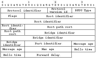
fig 2 - Configuration BPDU
Protocol identifier : takes the value 0 for spanning tree Protocol
Version id : takes the value 0
BPDU type : 0 specify a configuration
BDPU Flags : used to signal a topology change (bit 1)
4.2.- Topology change notification BPDU
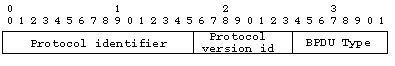
fig 3 - Topology change notification BPDU
BPDU type : takes the value 128
5.- IEEE 802.1D recommended values
Maximum bridge diameter recommended : 7
Parameter
Recommended value
Absolute maximum
Maximum bridge transit delay
1.0s
4.0s
Maximum BPDU transmition delay
1.0s
4.0s
Maximum message age increment overestimate
1.0s
4.0s
Table 1 - Transit and Transmission table
Parameter
Recommended or default value
Fixed value
Range
Bridge hello time
2.0s
-
1.0 - 10.0s
Bridge max age
20.0s
-
6.0 - 40.0s
Bridge Forward play
15.0s
-
4.0 - 30.0s
Hold Time
-
1.0s
-
Table 2 - Spanning Tree algorithm timer values
Parameter
Recommended or default value
Range
Bridge priority
32,768
0 - 65,536
Port priority
128
0 - 255
Table 3 - Bridge and Port Priority parameter values
Link speed
Default value
Recommended range
Range
4 Mbps
250
100 - 1,000
1 - 65,536
10 Mbps
100
50 - 600
1 - 65,536
16 Mbps
62
40 - 400
1 - 65,536
100 Mbps
19
10 - 60
1 - 65,536
1 Gbps
4
3 - 10
1 - 65,536
10 Gbps
2
1 - 5
1 - 65,536
Table 4 - Path Cost parameter values
©2001-2022 Karpok - Contact me